This will invalidate your warranty and could be a terrible idea – I haven’t fully tested this yet!
If you are using MAPIR cameras on a 3DR Solo drone, you might want to dispense with the camera battery packs (which aren’t great) and power the units through the microUSB socket. To do this, you’ll need to find 5v from inside the airframe. I’ve done this by piggybacking a UBEC onto the main power rails and connecting two microUSB leads. Here’s how I did it:
Parts & tools required:
- microUSB plug to bare-ends
- Double-sided sticky foam fixing
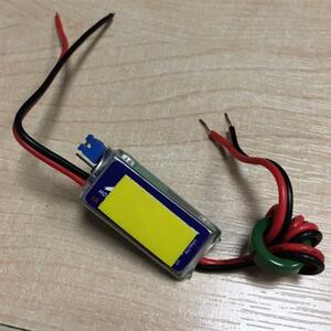
- 2s-6s to 5v UBEC
- Crosshead screwdriver
- Square nosed pliers (optional)
- Small cable ties
- Spudger
- Soldering iron & associated bits
- Heat-shrink tubing
- Hot glue gun
- Insulating paint (a.k.a. “liquid electrical tape”, optional)
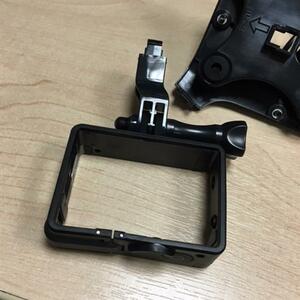
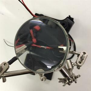
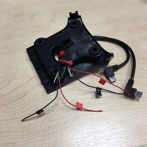
- Remove the static gimbal and dis-assemble it to remove the GoPro frame (use square nosed pliers). This only wants removing if it’s surplus to requirements; you could leave it on.
- Cable tie the two microUSB to bare end wires onto the side of the frame.
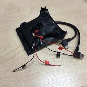
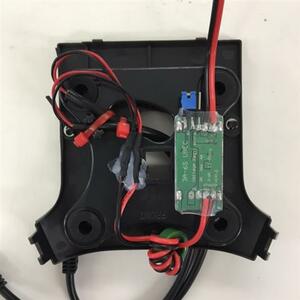
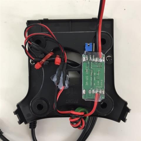
- Place a strip of double-sided sticky foam fixing to the UBEC & configure the UBEC for 5v output. Affix it to the top of the static gimbal frame.
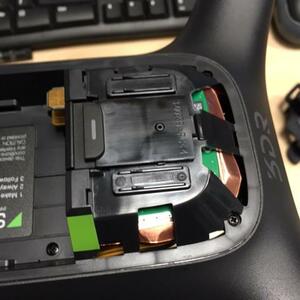
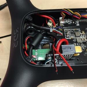
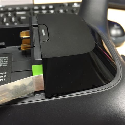
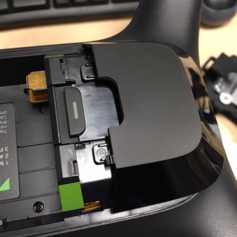
- Use a spudger to remove the top cover adjacent to the battery compartment.
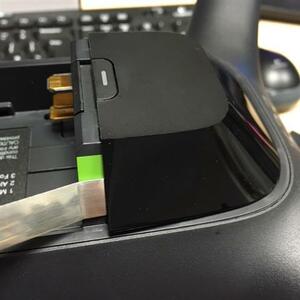

- Unscrew all 7 screws to remove the top tray, careful to disconnect it from the main board as you remove it.
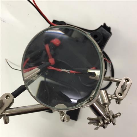
- Solder the +ive and -ive power wires from the microUSB plugs to the +ive and -ive output wires from the UBEC. Use heat-shrink tubing to cover the join & secure the cables using some hot glue.
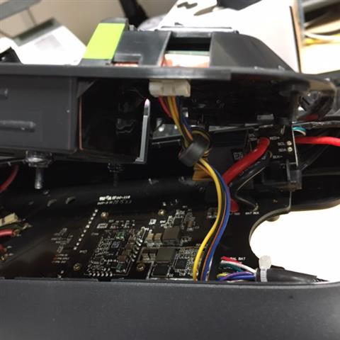
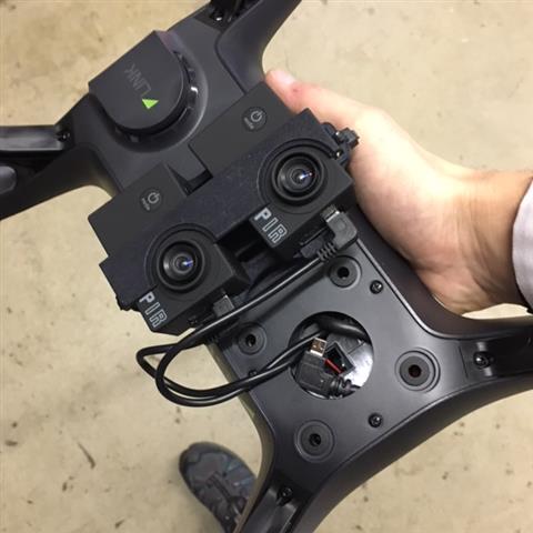
- Reinstall the static gimbal, feeding the UBEC power input wires up above the main board, and the video connector (miniUSB) down through the static gimbal.
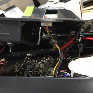
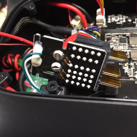
- Unseat the main power connector board (it is simply clipped in).
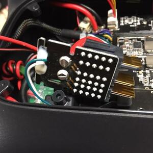
- Solder the +ive and -ive UBEC input wires to the main power terminals.
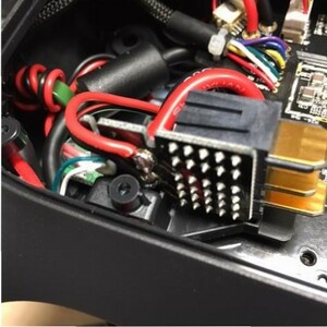
- Cover with insulating paint (if, like me, you worry about how close those two main connectors seem to be!).
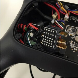
- Replace the main power connector board, top tray connection and top tray, fix the camera mounts and test.


I suppose it could be possible to find 5v somewhere else – I can see a couple of terminals on the main board marked 5v, but I have no idea what kind of draw they can handle or whether they are always on, so the UBEC seemed to be the simplest option, if not a little invasive. If I were to change anything I’d add an inline plug and socket to the UBEC, making it easy to remove if the gimbal wanted changing.