Introduction
A student recently came to us with a project that would make use of Dr Ian Walker’s bicycle overtaking sensor, so I agreed to make him one. Since Dr Walker published his original article, the code has had to change a bit, so I thought this would be a good opportunity to post the updated code and include a complete bill of materials.
Bill of Materials
- Arduino Uno rev.3, e.g. RS #715-4081
- Adafruit datalogging shield #1141 (I purchased from Pimoroni)
- Button battery, CR1220, e.g. CPC #457-4713
- header pins, 2.54 mm, e.g. CPC #CN18415
- SD card, e.g. Transcend TS2GSDC, e.g. RS #758-2552
- M3 self-tapping screws, 4 mm, e.g. RS #500-5094
- Sellotape Sticky Fixers, e.g. CPC #OE02909
- jumpers, e.g. CPC #SC12901
- heat shrink tubing, 3:1, 3.2 mm diameter, e.g. CPC #CB10468
- Maxbotix ultrasonic sensor (either a MB1200 XL-MaxSonar EZ0, or an EZ2); I bought from Cool Components (stock numbers #484 or #595 respectively)
- M3 standoffs, 6 mm, e.g. RS #222-373
- 4-way socket, e.g. CPC #CN14906
- 4-way plug, e.g. CPC #CN13577
- 4-way cable, e.g. RS #660-7067
- Power switch, e.g. RS #314-4995
- Crimp connectors, e.g. CPC #4217251
- Push button switch with light, e.g. RS #457-4713
- 3-d printed enclosure for the switch (click to download my *.stl file that fits the switch above)
- Bicycle flashlight holder, e.g. this item from eBay
- cable ties, 2.5 mm, e.g. CPC #CBBR6667
- AAA battery holders x2, e.g. RS #512-3552
- Enclosure, I used a Hammond 1591ESBK, e.g. RS #415-2846
Code for Arduino
You’ll need a USB cable to program the Arduino. I have made some modifications to Dr Walker’s original code. They address four points:
- The RTC (real-time-clock) used in the latest revision of the Datalogging Arduino Shield has changed. This addresses the changes needed.
- There is a new library available for the Maxbotix distance sensors which is a far more elegant than the old alternatives.
- I’ve decided to use the internal pull-up resistor on the button input, rather than an external pull-down. It saves on the wiring!
- I’ve added a serial output for checking the unit is working correctly.
The revised code is available here. Remember that the first time you use the RTC, you need to program it – instructions can be found here.
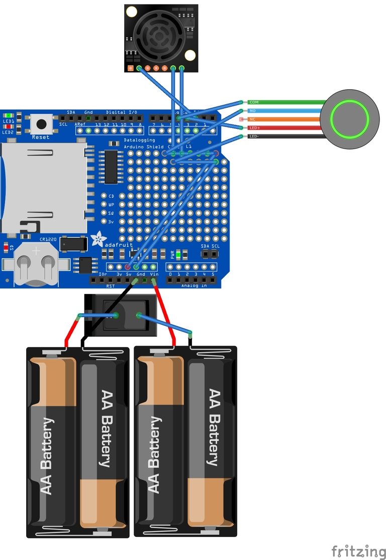
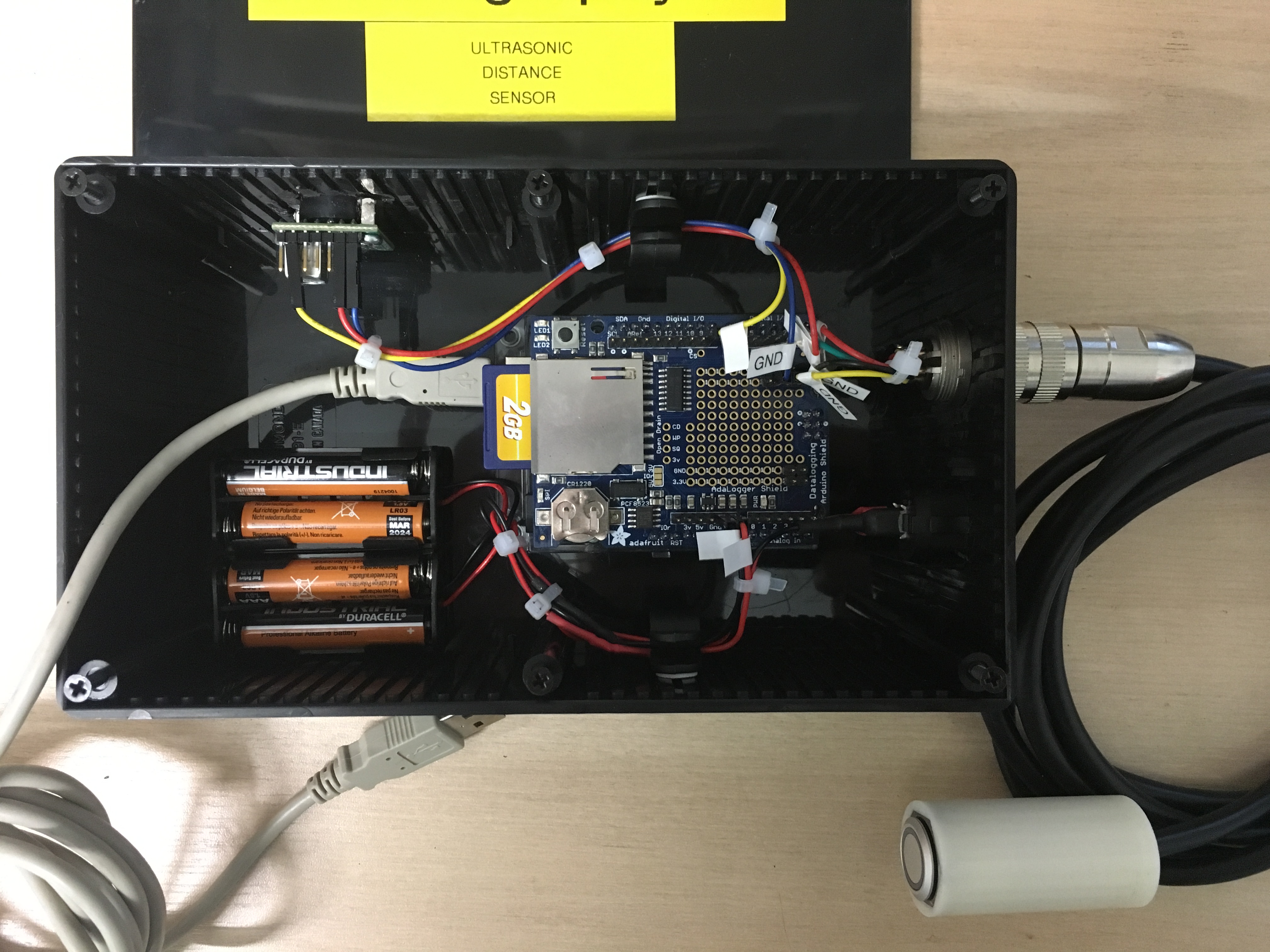
Building the Unit
It should be pretty obvious how this all goes together from the photographs, code and wiring diagrams, but a few hints:
- The handlebar button fits in the printed enclosure, and the cable can be secured with a cable tie to stop it pulling on the button connections. A tiny dab of super-glue holds the button in place.
- The Arduino and shield can be secured using the base plate that comes with all Genuino’s using the self-tapping screws, and the base plate secured in the enclosure using the sticky fixers.
- I secured the Maxbotix sensor to the enclosure by screwing two standoffs to it, and gluing the standoffs to the inside of the enclosure.
- I thought it easier to connect the power button using crimp connectors. This allowed me to easily fit the button to the enclosure. The battery holders are held down with sticky fixers.
Conclusions
I’ll update this section in due course when we have the results of the research conducted with this sensor!